This
article was published in ![]()
CNC drilling machine is a tool
which
is required for drilling of holes in PCB, thaw it can be used for many
other purposes too. The software communicates with machine via serial
port
(COM1...COM4) of PC. The software works
only with machine
which has the right micro controller built in.
TABLE OF CONTENTS:
WHAT IS CNC
DRILLING
MACHINE?
HOW DOES IT WORK?
CIRCUIT DESCRIPTION
MICRO CONTROLLER
OPERATION
AND ROUTINE EXAMPLES
ASSEMBLING THE PCB
HOW TO CONNECT A
STEPPER
MOTOR?
FIRST STARTUP AND
CALIBRATION
SOFTWARE
HOW
TO MAKE MECHANICAL PART OF MACHINE?
COMPONENTS LIST
DOWNLOADS
The name itself (CNC = Computer Numerical Control) says pretty much. The machine is intended to be used to help hobbyists with their prototyping. Also if you draw something else with your software, you can easily do other jobs as well. The machine described below functions like many others. That means that the computer transmits positions and commands to machine. The machine then executes desired operation and replies to the computer when done. In our case one part of job is done when one hole is drilled. This machine can't mill PCBs yet, but I'm working on it.
The machine I made works similar
like
other machines of this type. It is connected to serial port of IBM
compatible
personal computer and controlled by program written for MS Windows®
operating
system. The program transmits data from PC to machine and checks if
it's
responding. The machine replies every time when operation is done or
when
computer asks it if it is powered on. The program first sends
coordinate
for X axes, then for Y and finally for Z. After sending last coordinate
also the command is sent which tells the machine what to do with
drilling
head. That command can send head towards PCB, it can drill a hole of
certain
depth, which means that the head will go down for certain distance and
then move back up. It can also move head up or initialize it.
The core of machine is simple micro
controller AT89C2051, which is fully filled with program, written with
Bascom-8051. (By the way, thanks to mr. Mark Alberts for his wonderful
program) The mcu has a lot to do. It takes care of receiving and
sending
data, motor direction and pulses needed by motor controller, current
through
motors and driller power. It also calculates it's relative coordinates
from absolute ones, sent by computer. In fact it's really busy.
The core of our circuit is well known micro controller AT89C2951. It works at 12MHz, which isn't ideal for baud rate generator, but it works fine. Most of I/O pins have external pull-ups except P1.1 which is used to control current flow through motor windings. Reason for this are interference's generated by motor current control. The capacitors C13, 18 and 23 are therefor the same reason. P3.1 and P3.2 are used for PC communication.
C24 (470n) is used as reset capacitor who's pull down resistor is in already in micro controller. I thought it makes no sense to put external electrolytic capacitor and pull down resistor in such cases. The MAX232 is also well known RS232 level converter. These two circuits are powered from +36V line via 15V zener diode and 78L05 voltage regulator. I decided for this because translators L297 generate much noise in their power line. +5V power supply for L297 must be connected externally.
I also included drilling machine's power supply in my circuit. It is configured for 12V motor. If you use other motor voltages you should adjust components in this circuit, specially RE1, C1 and power transformer.
At the end there are motor controllers which are well described in ST's data sheets. I should mention that JP1, JP3 and JP4 are used to set step mode of motors; half step or full step. With half step we double motor's resolution and exclude spurious resonance, but we also loose some torque. There are also two points marked with SP1 and SP2. These are spare connections and are not used yet.
Micro controller also takes care of motor current. The voltage divider is made with resistor 2k2, and trimmer 470R. When P1.1 is low the divider is additionally pulled low via 180R resistor. This way we reduce standby current to 1/3 of full current. This way motors stay cool when the machine isn't in use. The current through each motor is controlled with 470R trimmer potentiometers TP1, TP2 and TP3. The power loss on output chips depends on motor currents and chopper frequency. Probably you will need a smaller cooler and maybe a little fan on top of it.
The power of power supply required
by
our circuit depends on motors we use. In most cases the 36V/2A and
5V/0.3A
PS will do fine. The cable between PC and driller is usual with two DB9
connectors, male and female. The initialization switches are normal
mechanical.
I decided so, because they aren't sensible to light or dust like IR.
Note: if the
schematics
doesn't load, hold SHIFT and click on picture to
save it to disk and
then
open it with your favorite image viewer.
The same goes for other
High resolution images too.
Circuit schematics
MICRO CONTROLLER OPERATION AND
ROUTINE
EXAMPLES
On power on the micro controller
first
initializes all three motors. First it lifts Z motor on top, to avoid
drill
breaking. If the motors are in initial position, they are moved a
little
and initialized back again. The motors run until they hit their end
switch.
The mcu then stops that motor and initializes next one. The
initialization
routine looks like this.
'Z axis initialization
If P3.5 = 0
Then
'if the end switch is pressed
P1.3 =
1
'set motor direction to CW
For N = 0 To 100
P1.2 =
0
'reset CLOCK line
Delay
'wait a moment
P1.2 =
1
'set CLOCK back
For J = 0 To M 'with this loop we set the
Delay
'speed of motor by changing
Next
J
'the pause between CLOCK pulses
Next
N
'repeat this 100 times
End If
P1.3 = 0 'set motor direction to CCW
Do
'repeat following routine
P1.2 = 0
Delay
Delay
P1.2 = 1
For J = 0 To M
Delay
Next J
Loop Until P3.5 =
0
'until the switch is pressed
The same happens for X and Y axes too. When initialization is done, the MCU sends message to PC that it's ready.
Print "Ready";
After that it waits for computer
commands.
It's interested in coordinates and command which tells it what to do.
The
computer asks MCU if it's ready before starting the job. If he doesn't
get any reply from machine he warns as with error dialog. If the MCU is
ready, then computer sends him the first coordinate with a command what
to do when it gets there. When the driller is in position, it can do
the
following:
Print "Done";
When PC receives the reply from MCU it sends him next coordinate, if necessary. MCU receives coordinate with following routine:
Pom1 =
Waitkey
'reads 5 variables
Pom2 =
Waitkey
'from serial port
Pom3 = Waitkey
Pom4 = Waitkey
Pom5 = Waitkey
Num =
Chr(pom1)
'converts from character to ASCII
Pom1 =
Val(num)
'converts from ASCII to integer
Temp = Pom1 *
10000
'multiply with 10000
Num =
Chr(pom2)
'again convert char
Pom2 =
Val(num)
'to integer
Pom2 = Pom2 *
1000
'and multiply it with 1000 and
Temp = Temp +
Pom2
'add it to previous temp variable
Num =
Chr(pom3)
'do the same for
Pom3 =
Val(num)
'hundreds
Pom3 = Pom3 * 100
Temp = Temp + Pom3
Num =
Chr(pom4)
'tens
Pom4 = Val(num)
Pom4 = Pom4 * 10
Temp = Temp + Pom4
Num =
Chr(pom5)
'and ones
Pom5 = Val(num)
Temp = Temp + Pom5
X = Temp 'at the end assign this variable to X
The computer sends absolute
coordinates
to computer. The MCU then calculates relative coordinates (number of
motor
steps).
Clkx = X –
Xs
'he calculates nr. of steps from old value
Xs =
X
'and saves value of new coordinate
If Clkx > 0
Then
'assign motor direction
Dirx = 1
End If
If Clkx < 0 Then
Dirx = 0
End If
Clkx =
Abs(clkx)
'calculate absolute number of steps
Then it moves on desired position.
Do
If Clkx > 0
Then
'if number of steps is greater then 0
P1.6 =
0
'generate clock
Decr
Clkx
'and subtract one
End If
If Clky > 0
Then
'repeat the same
P1.4 =
0
'for Y axes
Decr Clky
End If
Delay 'wait a moment
P1.6 =
1
'end clock pulses
P1.4 = 1
For N = 0 To
M
'generate a delay
Delay
'which determines
Next
N
'motor speed
If Clkx = 0
Then
'when nr. of steps on X axes is equal to 0
If Clky = 0
Then
'and nr. of steps on Y axes also equal to 0
Exit
Do
'end loop
End If
End If
loop
Print "Done";
That's all about main routines. Some of them are repeated several times, but I explained only the main examples.
If you are going to make the PCB at home, you will encounter a problem, because it's double sided with lots of vias. I suppose that best way to make a professional PCB is to have it done by PCB manufacturer. The plans for pcb and all other stuff you can get at the end of this document.
When you have your PCB done, you can
start soldering SMD components. All 100n capacitors are filter
capacitors
for power supply. If you don't have 100n you can use greater values as
well. They should be dimensioned for 50VDC and preferred size is 1206.
SMD components layout (bottom side)
Then follows soldering of "normal"
wired
components. First solder the lowest components and then proceed to
higher
ones. Please, use sockets for DIL chips. The diodes must be 2A/100V
fast
recovery. FE2B can be used from Diotec.
ICs L298N must be cooled properly.
they should be attached on heat sink WITH
INSULATION
BETWEEN HEAT SINK AND ICS. THE THERMO CONDUCTIVE PASTE MUST BE USED!
Power supply connections are made
with
screw type connectors assembled from three pieces (3+3+2 pins). As
motor
connectors I used Speedy 10 pins connectors with flat cables and two
wires
for one connection. That means that 8 pins are used for 4 wires. The
last
two are used for end switch. (pin 9 = hot, pin 10 = GND) Be sure not to
short circuit the motor cables. The current regulator cannot limit
current
fast enough, since short circuit means only a little inductance.
Components layout (top side of PCB)
HOW TO CONNECT A STEPPER MOTOR?
As we know, there are two basic
groups
of stepper motors, looking from point of coil connections. Unipolar
motor
has four coils (or two coils with center connection, if you wish) and 6
wires on outside. Some of them have center of coils connected together
and have only 5 wires on the outside. Bipolar stepper motors have only
two coils and four wires on outside. Considering that our circuit is
intended
for driving bipolar motors we will have no problem connecting bipolar
motor
to our circuit. If we want to connect a unipolar motor then things get
a little different.
Since unipolar motor has center
connection
on each coil, we can leave this connection free (NC) and, as you se on
schematics of motor, by doing so, we transformed this motor to bipolar.
Only problem is coil resistance, so we should choose this option when
coil
resistance is low and motor is made for low voltages (3 to 5V). If it
is
too high, the current won't reach it's nominal level and the torque
will
be lost (Variant 1). In this case we can disassemble motor and brake
connection
on middle terminal and then connect coils parallel, as it's visible on
picture, variant 3. If you don't need motor's full torque, you can
connect
it on one of the side wires and on center wire, as you can see on
variant
2. Maybe someone will ask why don't we just connect the side wires
together
and we would get lower resistance for variant 3 without disassembling
the
motor. But this won't work, since the coils are winded bifilar and
magnetic
flux would be compensated.
IMPORTANT!
Variants of motor connection
We'll achieve best results with
motors
designed for 4 to 10V and for currents between 0.2 and 1.5A.
Don't try to power on the machine
without
a cooler on output stage IC-s since they cam be burned very quickly (I
should know, unfortunately). The trimmer potentiometers must be in
final
CCW position. You can connect motors for testing right on your desktop.
The end switches you can simulate with some keys or switches. Be sure
you
assembled all as described and as seen on component layout pictures. If
you checked it all twice, you can power on your circuit and slowly turn
the TP3 (Z axis trim pot) in CW direction. The motor will start
turning.
Maybe at certain current, specially when full step is selected, the
motor
will start behaving strange. This is due to motor's resonance, because
it is not loaded. This phenomena will disappear when motor will have a
load to carry around. When you press on that mtor's end switch then the
X motor will start turning (after current adjusting procedure). Press
on
it's end switch as well and then repeat all this for Y axis motor. When
all of this is done and if PCB is connected with your computer, you can
start Easy NC drill program, described below, open file for drilling
and
press Start. The motors will start turning as they will later, when
they
will be fastened in their position. If any of motors has wrong
direction,
just swap the two wires of one of the coils. If the motors get hot,
reduce
the current.
If all of this works for you, you are
really on a good way to make the final product working. Congratulations.
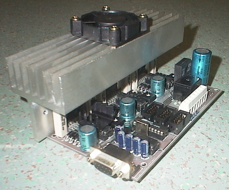
Assembled PCB prototype
The software for controlling of our machine is written for MS Windows® operating system. I tried to implement as many functions as possible, tow I know that many things can be done better. Any ideas and suggestions are welcome.
The recommended hardware
configuration
is:
The program Easy NC Drill reads standard drilling files (*.NCD) generated by various PCB designing programs, but there are some settings to be carefully set in order to make file readable by Easy NC Drill. These settings are:
Units: Inches
Code: ASCII None
Zero Suppression: Trailing
The CAD program will this way generate a file that will be understandable by Easy NC Drill. I made an example of file which has only one tool and three holes. On the beginning of file there must be line with text M48 or M72, otherwise the file will be considered of wrong format.
M48
INCH,LZ
T04F00S00C0.030
%
T04
X+002Y+004
Y+002
X+003Y+003
T00
M30
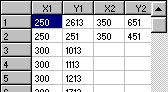
Easy NC Drill supports up to eight
different
tools and 1000 holes of each one. When you open the file, the
coordinates
are visible in table on the left side of screen.
When you have a file opened and all settings set you can start drilling. Many of settings are those, which are set only once for your machine and others may be set several times. The settings are available by clicking on button, via menu or shortcut keys. So, lets take a look of these settings:
Warning! Some names of settings may be changed in the future.
Communication
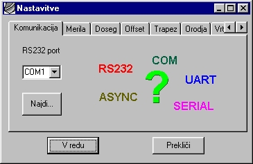
Under Communication tab you can
choose
a port that your machine is connected to. If you don't know which one
is
it, you can click on the Find button and machine will be detected
automatically.
There are no other communication settings necessary since they are
controlled
internally.
Steps Per Inch (SPI)
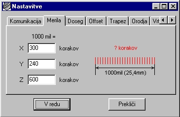
In these fields you can type how
many
steps does your machine have to do to "travel" 1 inch (25,4mm). You can
come to that numbers by trying. You can draw a PCB with four holes and
then drill it with machine and adjust parameters. The numbers are
usually
around 200 and 400 when stepper motor with belt directly on it's axes
is
used. If you use same motors for X and Y axes, the numbers should be
the
same.
Range
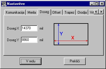
In these fields you should enter the
full range of your machine. This depends on it's construction and is
defined
in mils. These numbers you get by measuring of machine range with ruler
and subtracting about 2 mm of it. If you enter too big numbers, the
machine
can crash into the end mechanism.
Offset
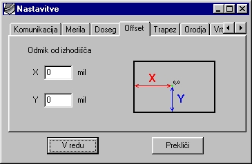
Offset tells us where the 0,0
coordinate
should be. Increasing offset means decreasing our active area of work,
so consider setting offset to minimum. Also offset can not be bigger
then
range anyway. The offset coordinate is ignored when tool change
coordinate
is sent.
Trapezoid
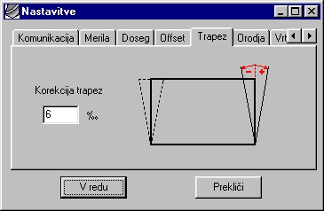
The trapezoid distortion occurs, when machine mechanics is not mad enough precisely (90°angle between X and Y axes) or when you use laser printer it's output can be distorted too. Usually you don't notice that. I didn't too until I had to drill PCBs made with laser printed film. We can test machine and printer the same way. Draw a rectangle and print (drill corners of) it. Then measure opposite points. Maybe you'll be stunned with results. I measured difference on one Epson laser. It was almost Num! The value can be positive or negative.
Tool change
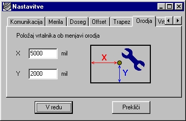
In these fields we enter coordinate
for tool change. This is a position where the tool is most easily
exchanged.
If enabled, the machine will go to this coordinate every time the tool
has to be changed.
Head
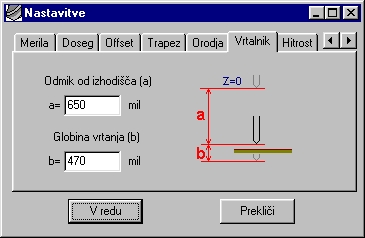
Under mark "a" we enter offset from
initial position on top to the PCB's copper layer. We should leave 1 to
2 mm for safety reasons, otherwise the drill can break if it hits
something.
Under "b" we enter drilling depth.
This depends on thickness of our board.
Speed
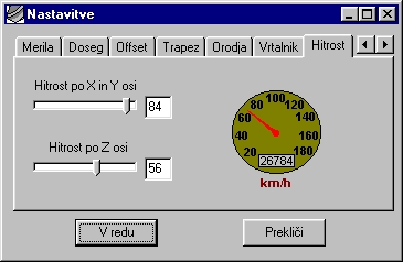
The speed can be set for X and Y axes together and for Z axes. The number we enter tells the micro controller how many delays he should make between motor's clock pulses. Higher value faster transport. Speed must be set in reasonable limits. If it's too slow, drilling will take a while, if too fast, the motors can loose their position on startup and board will be ruined. Speed of motors depends on machine design, motor torque and motor current. You can get your value with testing.
When you're done with setting parameters click the OK button and settings will be saved to program and to hard disk in file cnc.ini. Settings are also saved when you exit the program.
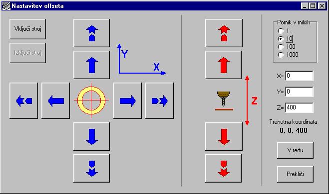
Offset (again? nooop)
In latest version of Easy NC Drill I implemented setting of offset when machine is running. By clicking the buttons you move it to certain point and then hit OK when you are done. By default the machine is turned off. If you want to turn it on, click the button Machine ON and it will go to offset position.
I should mention some other settings, which are not available from settings window. They are available only in program's main window.
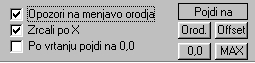
Warn for tool change
If this box is checked, the program will warn you every time the tool should be changed. The drill head will go to coordinates set in Tool change settings window. The dialog will also tell you which drill diameter is next. If unchecked, the machine will not ask anything while drilling and all holes will be done with the same diameter.
Mirror X
If this option is checked, the image and drilling path will be mirrored. This option is very usable, since we design PCBs in "top view" mode, but when we want to drill, we do it from copper side of board, if PCB is single sided.
Go to 0,0 when done
If this option is checked, the
machine
will go to 0,0 when the job is done, otherwise it will go to Tool
change
position.
O.K. So now the tool bar is next. The commands on toolbar are the basic ones.

Open NCD
Opens file with extension NCD in
last
used directory if possible. If file format isn't supported or if the
coordinates
are out of range the error message appears. In case that coordinate is
out of range it's possible that we made our project far from bottom
left
corner. Usually the easiest solution is to move our PCB in bottom left
corner or to put origin point closer to our project.
Drill
Well, I guess we'll need this one.
It
starts the machine and executes selected job. If the machine is powered
off or if it's COM port isn't properly selected the message will warn
us,
that the machine isn't responding. Also it will warn if no job is
selected.
Stop
Press stop when you want to end
drilling
prematurely. A dialog for confirmation will appear še
.
Settings
Opens dialog with settings mentioned before.
Offset
Opens dialog with offset settings mentioned before.
About
Opens dialog with some program info and links to this page.
Exit
Closes program and saves it's
settings.
There are four speed buttons in right upper corner for sending machine to some often used coordinates:
TC means tool change position, Offset means offset position, 0,0 means position 0,0 and MAX means maximum range position.
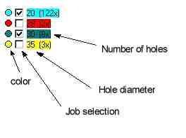
Some of options are not visible until a file is loaded. In upper left corner of "drawing surface" the painted circles with check boxes, drill diameter and number of holes are shown when the file loads. The circle paint corresponds to paint of holes on drawing surface. You can select type of holes to be drilled by checking the appropriate check box.
During the drilling process you can monitor it on screen. Finished holes are marked with red cross and driller path is colored green. We can also trace progress on two progress bars in status line.
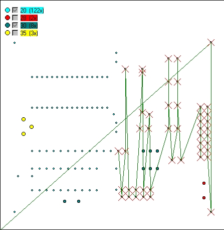
Job in progress
HOW
TO MAKE A MECHANICAL PART OF MACHINE
I personally think, that making machine's hardware is the hardest thing to do. The prototype I made isn't very neat, but it works quite well. The main issue from my point of view was product's price. I wanted to make a machine that would be very cheap. I guess in your country, which ever it is, there is a lot of junk computer equipment and that's very nice, since we don't have to buy the expensive stepper motors.
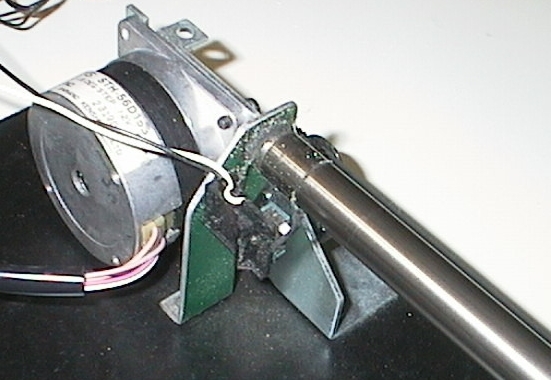
I will explain how I made my machine
and where I got my parts. The motor which drives machine in X axes and
all mechanics around it was taken out from an old scanner. The motor
should
be one with 200 steps per revolution (1,8° step angle) and strong
enough
to move other mechanical parts around. You can see the motor and "home
switch" on the picture below.
The mechanism of Y axes is fastened
on the arm, which is driven by X axis motor.
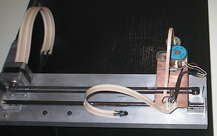
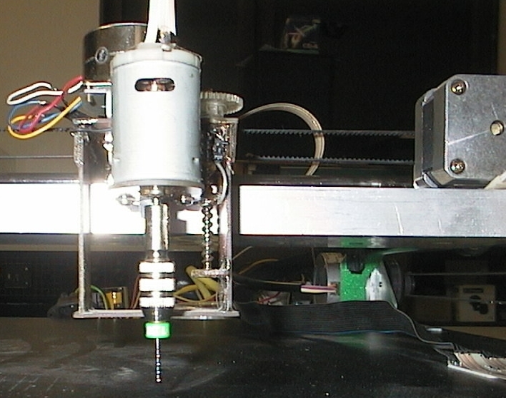
The smaller motor is driving Y axis
on which the driller is fastened. The third motor, which drives driller
on Z axis can be connected directly to spiral axis if it has high
enough
resolution, otherwise it should have a gear transmission like in my
case,
where the motor is 7,5°. As you can see the mechanism which holds the Z
axis is made from PCB material. It isn't very neat, but it works. The
only
problem is it's stability which is quite gentle due to weaker
construction.
But it's prototype anyway.
The swirly axis i took out of an older, double speed Mitsumi CD-ROM, the "guides" (I don't know the right word for it but I mean that metal stick on which everything slides.) are ones from old floppy disk units. The motor and mechanism of X axes is from old scanner and of Y axes from Epson Stylus 400 printer. The power supply is also from this printer.
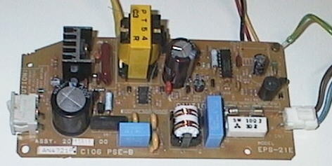
The motor of Z axes is from Canon's typewriter, the flat cables are from steering wheel of Fiat's Bravo (Air bag connection). You can also use cables from old dot matrix printers which lead to printing head. All together is mounted on 16 mm wooden board and it is quite fine. The driller is a little motor with drilling head.
COMPONENTS LIST
| Label | Value | Pcs | Comment |
| R1 | 22k SMD | 1 | Size 1206 |
| R2, R3, R5, R6, R8, R9 | 0,47R/2W | 6 | Vertical mounting |
| R4, R7, R10 | 2k2 SMD | 3 | Size 1206 |
| R11, R12, R13 | 180R SMD | 3 | Size 1206 |
| R14 - R25 | 5k6 SMD | 12 | Size 1206 |
| C1 | 2200u/25V | 1 | |
| C2, C3, C5, C6, C8, C10, C12,
C14,
C15, C17, C19, C20, C22, C27, C28, C33 - C35, C37- C39, C41 |
100n SMD | 22 | Size 1206, can be replaced with greater values, 220n for example. Not critical. |
| C4 | 47u/25V | 1 | |
| C7 | 4u7/25V | 1 | |
| C9 | 2,2n SMD | 1 | Size 1206 or 0805 |
| C11, C16, C21 | 470u/40V | 3 | |
| C13, C18, C23 | 1n SMD | 3 | Size 1206 or 0805 |
| C24 | 470n SMD | 1 | Size 1206 |
| C25, C26 | 33p SMD | 2 | Size 0805 |
| C29 - C32 | 1u/25V | 4 | |
| C36 | 100u/63V | 1 | |
| C40 | 47u/6,3V | 1 | |
| D1 | 1N4148 SMD | 1 | |
| D2 - D25 | FE2B | 24 | 2A fast recovery |
| IC1 | LM78L05 | 1 | |
| IC2, IC4, IC6 | L297 | 3 | |
| IC3, IC5, IC7 | L298N | 3 | |
| IC8 | AT89C2051 | 1 | must be programmed with propper software. Get DEMO VERSION |
| IC9 | MAX232 | 1 | |
| ZD1 | BZX85, 15V/800mW | 1 | |
| RE1 | JSM1-12V-4 | 1 | or similar with same footprint |
| T1 | BC239C | 1 | can be any other NPN
with hFE > 200, Icmax 200mA and Ucemax 40V |
| TP1, TP2, TP3 | 470R | 3 | trimmerpotentiometer, horizontal |
| GR1 | B20C2300-1500 | 1 | rectifier for 2A/40V |
| X1 | 12MHz | 1 | |
| JP1 | 2 pin | 1 | WITHOUT JUMPER! Close only for reset. |
| JP2 | 3 pin | 3 | Select half or full step |
| CN1 | In line screwdriver connector, 7 pin | 1 | Can be assembled with 3+2+2 pin |
| CN2, CN10 | DB9FA | 2 | Female adapter |
| CN3, CN4, CN5 | Speedy 10 M | 3 | Male |
| CN6, CN7, CN8 | Speedy 10 F | 3 | Female, for flat cable |
| CN9 | DB9MA | 1 | Male |
Easy NC Drill V2.2.3 Download
TERMS AND CONDITIONS OF SOFTWARE USE
The Easy NC Drill software is freeware. It was made as a hobby project and is not intended to be sold. You can freely copy and distribute it if you wish. It is brought to you as is with no warranties of any kind. By using this software you agree with all terms and conditions of use written on this page. The CNC Drilling machine is dangherous. Use of the machine and software is at your risk. I'm not liable for any consequences made with it.
I agree with terms and conditions I don't agree with terms and conditions
NCD file examples Downloads
PCB in PostScript or Corel Draw 7 format
Included PCB film for top and bottom side and components layouts on top and bottom side.
Microcontroller firmware in HEX format (DEMO)
Author:
Srecko Lavric
Stare Zage 4
SI 8350 Dolenjske Toplice
