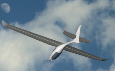
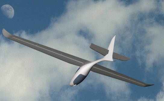
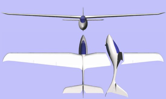
FANTASY, FOOTLAUCHABLE MICROLIGHT SAILPLANE
FANTASY is foot launchable ultralight sailplane with capability to launch on ordinary hang gliders sites. Start and landing are easy by use of large span flaps.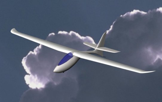
PERFORMANCE
GOALS:
HANDLING
GOALS:
SAFETY
GOALS:
WHY DESIGNING (BUILDING
AND FLYING) FOOT LAUNCHABLE SAILPLANE WITH SUCH POOR
PERFORMANCE?
Well I am hang glider pilot
since 1979 and even flying the sailplane for around 45 hrs solo, I am stil
emotionally attached to foot launch comunity and hang
gliders.
I think it will be fun to
show up on a hill with such design and having fun simply soaring on ridge
updraft or nearby thermals, beside hang gliders and paragliders, but having 3
axes aerodynamic controll over glider…
The main purpose of this
glider would be to made some futuristic design with no similiraty with present
foot launchable sailplanes as:ULF-1, Carbon Dragon, Super Floater, Swift and
other different types of tailless rigid wings.
The design should be of
simple construction adapted for the homebuilders. There is not an attempt to
commercially use of this design.
To achieve safety, handling
and performance goals I decided so:
HORIZONTAL TAIL
They are as follows:
1. cockpit area with nose cone and two cockpit
sidewalls
2. central part with two main bulkheads and wing
attachment points
3. tail cone with rudder fin
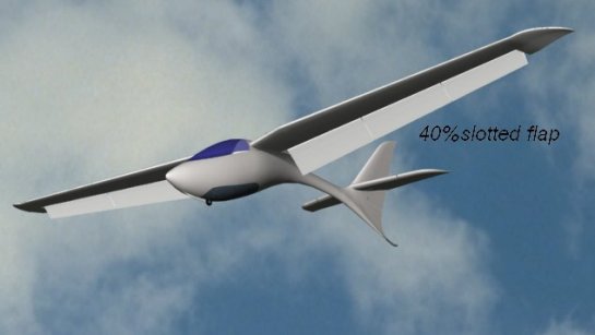
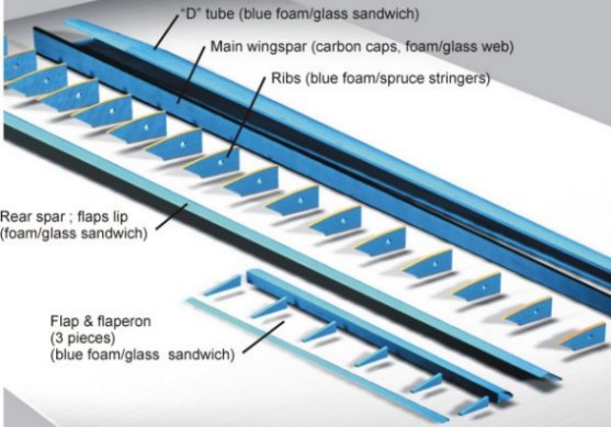
-WHY ARE THE FLAPS DIVIDED
IN 3 PIECES?
Because the wing will
defenetly be bend up during flight, the invisible »hinge line« of flaps wil be
distort from ideal straight line to some kind of arc. If flaps were hinged say 3
times per halfspan, it will be hard to rotate flaps (midle hinge not in line
with outer ones), and flaps will be stressed much more, because it should be
bend at unpleasant direction. At flap retracted it will bend at same manner as
main wing, but at deployed flap it looks that trailing edge of the flap will be
stressed in tension, and will probably break. This hinge missaligment would
probably cause some extra friction in hinges thus rising the command forces to
operate flap…Carbon Dragoon fight this with differential drive 1:4 (+4/-16 if I
remember right)
If we take a piece of paper,
and bend it at long edge (performing simplified shape of wing with deployed
flap) we soon discover that if trying to bend the wing, the bended part- flap,
will take almost all bending load. I dont want to flap take any necessary load
in my design.
So, if I divide flap into 3
parts per halfspan and hinging each part only twice (with ball bearings) I avoid
almost all unwilling stresses of the flap, regarding any wing bending (in
aeroelastic range of operation). Well, the gaps between flaps panels will
decrease their effectivines to some degree, but the gap can be filled with some
kind of foamy material, to avoid air leaking..
-WHY ONLY OUTER PART OF FLAP
ACT AS FLAPERON?
The simpliest way (for
calculations and aso for manufacturing reasons) is to use so called flaperons on
wing for both function (high lift device + controll over bank angle) as is done
at Carbon Dragon.
But I prefferd to divide
them into 3 parts and to use inboard two sections to act as flaps and outer one
as flaperon. Why?
If we imagine ourself just
prepared on the hill for launching, we want to have all benefits
of our high lift device. So, any change of flap(eron) setting toward up, wil
cause less lift. But we want all lift we can get from the wing at such low
speeds during starting phase. If we must rise or lower the tip of wing (if
sudden gust on start put the wing out of level attitude) we must produce a roll
moment over centerline of sailplane. This is simply done by changing the lift
force on wings. But the same moment we get if we produce big force somwhere at
mid span, or much smaller force at the verry outboard part of
wing.
I decided to use smaller
force at the tip part of the wing, so there are placed ailerons. They are
flaperons, because mechanically they follow the general motion of two inboart
parts of flaps.
Because wing is already at
high angle of attack (stil talking about take of phase) and almost the
highest CL, the ailerons in this case should move up only. In flap retracted
case, (talking about normal flying) ailerons attain full up and down
motion - diferential of course to fight adwerse yaw.
The mechanical device is not
yet taken in concern because I think it is possible to design such mechanism and
it is now out of scope of this discusion and at present design stage. But
will be soon actual…
With this arangement my wing
will loose minimal of lift force during aileron operation.
REM:I am afraid that long chord flaperons over full span when
deployed and then additionnaly deployed down (and on other wing up) for roll
motion, will produce big controll forces and troubles balancing and overcoming
them…
-ABOUT RUDDER
CONTROLL
During my past 22 years of
hang gliding I saw a lot of bad startings and many of them was when some gust
push one wing up, and then glider tend to make circle and hit back to the hill.
If pilot act too slow there is a danger, and also if pilot sudden »pull up« the
high wing gets into stall and we are again back rotating toward the hill. Here I
believe that prompt and exact respond of the pilot is crusial, and also the
respond of sailplane to pilots controlls…
So, I think that all
controlls should be »under controll« during take off to allow the pilot to
instantly correct any deviation from planned motion of the craft. Well,
sailplane is maybe of enough stability around all axes, but we can not controll
nature of the wind over the microlocation of starting place.
Because pilots legs are too
busy runnung at this point, the ruder pedals are free. They are forced into
center position via bungee cords or springs. But in the same time they are
connected with side stick mounted at left side of cockpit, so any action to
rudder is available instantly. Because the ruder is aerodynamically balanced,
the stick forces should not be to big. When pilot retract his legs into cockpit,
they can take over ruder pedals, and side stick is not necessary to use
anymore.
REM: a pilot is
responsibile for the safety of his flight and on him is to choose the weather
situation apropriate for his glider type and his piloting skilss and of course
the type of flying he intend to do. If he made a bad decision, even fine plane
can act as bad and leed to disaster.
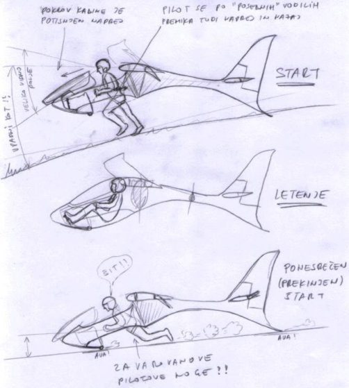
ABOUT ANGLE OF ATTACK AT
START
In my previous writting I
mentioned that it is not important to controll the wing angle of attack…(I
claim this only for my design and not for general at all) Well, in my
configuration the pilot is really free of concernig about the angle of attack
during start phase, because the design of fuselage take this responsibility. As
one of my sketches show, the pilot in the cockpit is unable to produce higher
angle of attack that his legs and tail resting on the ground
allow.
As we remember from
aerodynamical basics, the angle of attack is angle between direction of relative
wind and airfoil chord line. In starting phase of foot launched sailplane (or
any hang glider) the direction of relative wind is almost paralel to ground
where pilot take run, so angle of attack is stable and guaranteed, until
sailplane take off ground…then we fly, and angle of attack (speed) is pilot
responsibility..
REM: I doubt about
effectivines of elevator because of downwash produced by flaps…?!? L ! Still
loot of required thinking about tail volume, location, deflections,
airfoil..ooh! ..oh!!
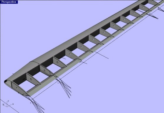
ABOUT MOLDLESS
FOAM/COMPOSITE CONSTRUCTION
It is possible to make
structural parts enough lightweight, I think…
First, I say bye bye to the
laminar flow around fuselage. If we want laminar flow ower fuselage, then
shape must be totaly diferent than my design. In moldless construction one
should achieve exact shape and streamlining without wavines, by filling,
sanding, filling, sanding, filling, sanding, filling, sanding, .. and this is
one of reasons for heavier structural parts. The wing in this building technique
(Windrose, Rutans designs,…) is generally heavy because the foam core represent
almost 1/3 of total wing weight…In my case I design hollow fuselage with inner
and outer skin. Outer skin should get only such quantity of filler and micro to
cover the weavines of the outer glass fabric ply and I will not bother with some
shape waviness that will cause early flow separation on high performance
sailplanes. We will just let them alone were they are. Let just take care, that
outer skin look straight and smooth for average eye…we not intend to competite
for best finish prize at one of famous Fly-Ins…we aim for pure strenght and
lightweight…
The fuselage core will be
reinforced with stringers of graphite (tape or rods..) and few
bulkheads.
ABOUT THE FLAP
DRIVE
I imagine, that flaps would
be deployed only before start and at landing. It will be better (safer) for
pilot to land on skid and sitting inside cockpit. It will be possible also to
land with flaps in zero position. If we estimate wing loading of 13 kg/m2 and CL max
=1,6 of pure airfoil, we can expect the stall speed about 40 km/h what is enough
low even to land safely with this (flight) confuiguration.
The question is only how
to reduce glide angle on final if field is short and it is to late to deploy
flaps. I dont like to put glider into slip close to the ground…it give me
strange uncorfotable feelings…Spoilers I dont like to put on the glider-one more
control system and added weight…
Any solution,
suggestion?
I
choose electrical driven flaps simply because In my case, they wil serve only at
start and at landing. Maybe some of the flaps will be needed during some thermal
circling..
I
think that one battery (usually used for electrical driven model airplanes, say
2000 mAh and 150W cheap can motor, with homemade gears) can serve during flight
and landing demands. Before start, when preparing the sailplane for flight,
pilot can mannually drive mechanism to flaps be deployed, and save some battery
power for later (in flight) use. The battery can be easily recharged with use of
charger and automotive battery in short time, when preparing for next
flight…
